Industry
Heavy electric actuators for locks, gates, slides and waterway infrastructure.
Lock and waterworks projects combine high loads, long service life, demanding surroundings and formal evidence, often in the context of public tender requirements. S+R sizes electric actuators so function, interface, calculation, documentation and later service fit together.
Typical tasks
Which motion needs to work reliably in this application?
slides and gates
waterway infrastructure
heavy positioning motion
service of long-running installed actuators
Requirements
Sizing starts with the environment, not with the nameplate.
long service life
This affects the design, spindle, motor, sensors, protection class or service access.
high forces
This affects the design, spindle, motor, sensors, protection class or service access.
moisture and corrosion-adjacent surroundings
This affects the design, spindle, motor, sensors, protection class or service access.
safety and documentation duties
This affects the design, spindle, motor, sensors, protection class or service access.
spare-part and service capability
This affects the design, spindle, motor, sensors, protection class or service access.
S+R solution route
Project requirements become a robust motion solution.
record load case and installation situation
The decision is documented so engineering, purchasing and service can understand why this route was selected.
check interfaces and safety reserves
The decision is documented so engineering, purchasing and service can understand why this route was selected.
document calculations and evidence
The decision is documented so engineering, purchasing and service can understand why this route was selected.
support service and recommissioning traceably
The decision is documented so engineering, purchasing and service can understand why this route was selected.
Technology building blocks
Proven design principles as a basis for individual solutions.
AP, SP and XP are not a rigid product logic; they are typical ways to build force line, installation space, protection and control.
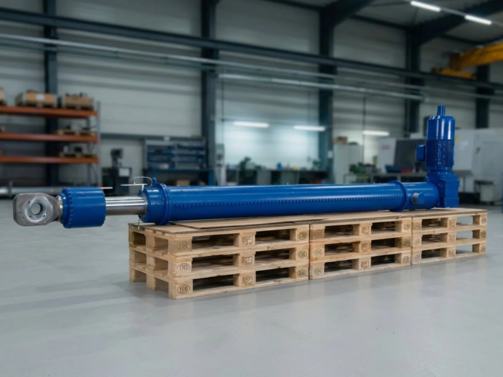
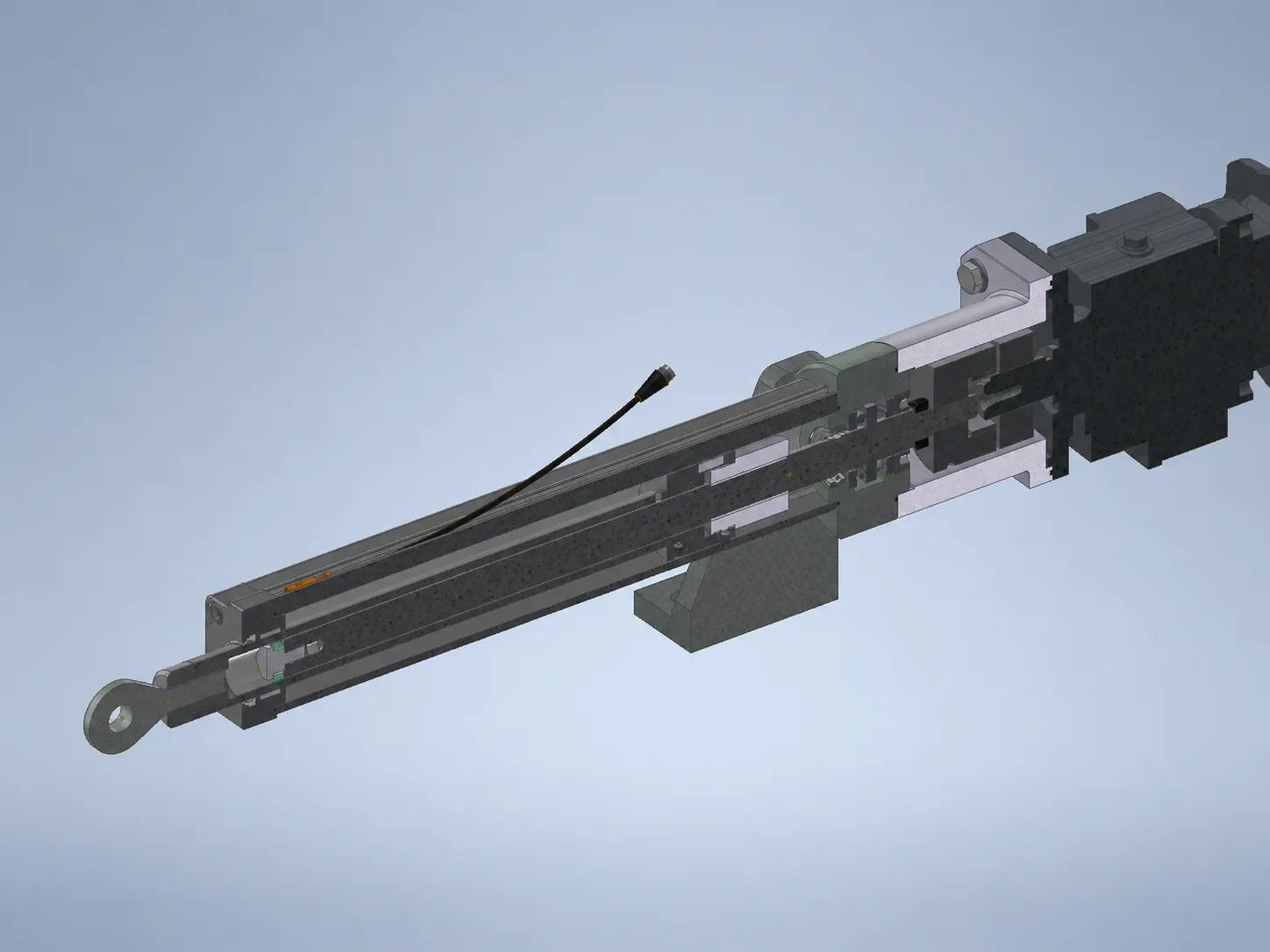
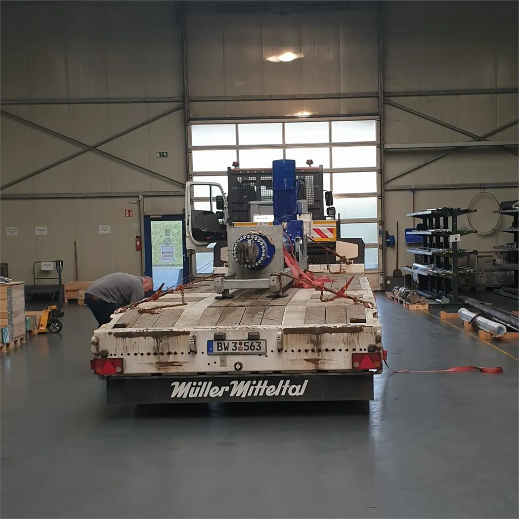
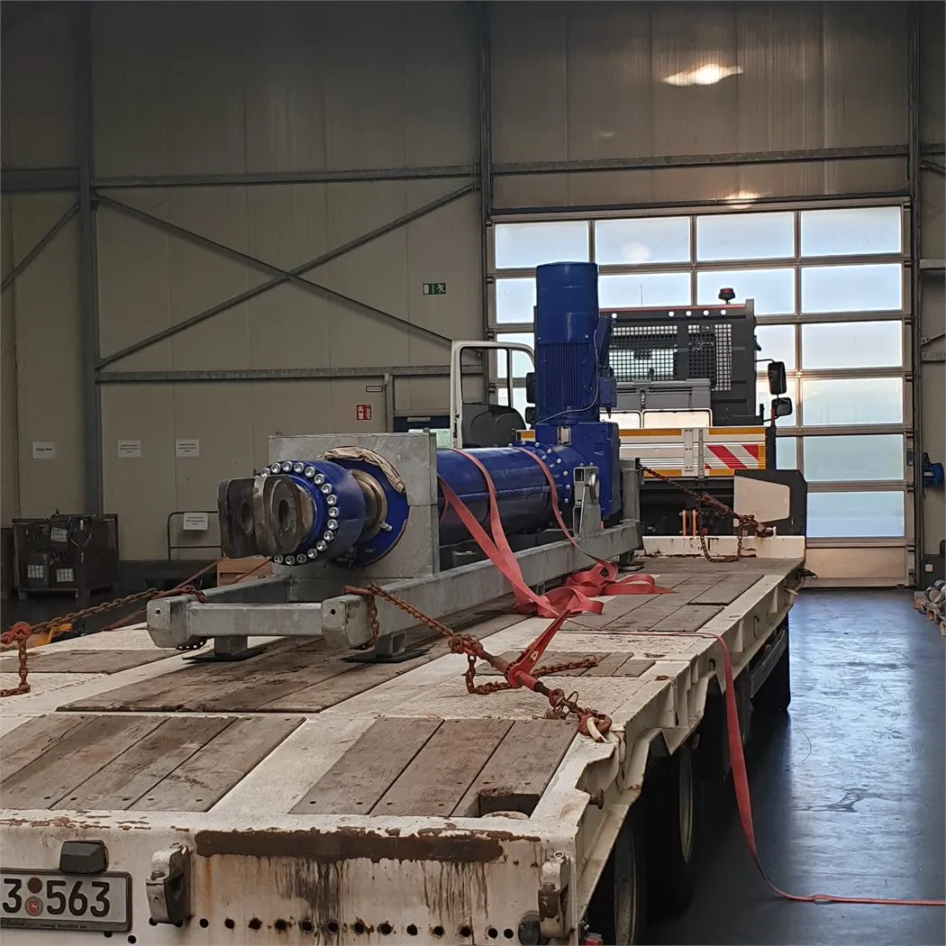
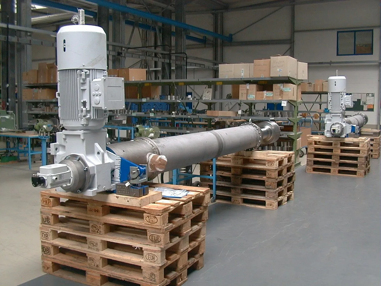
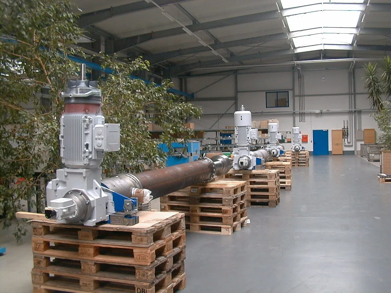
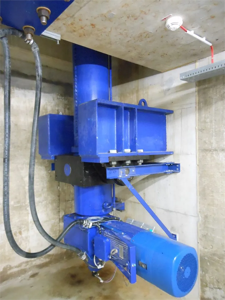
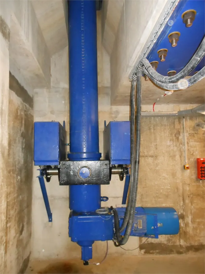
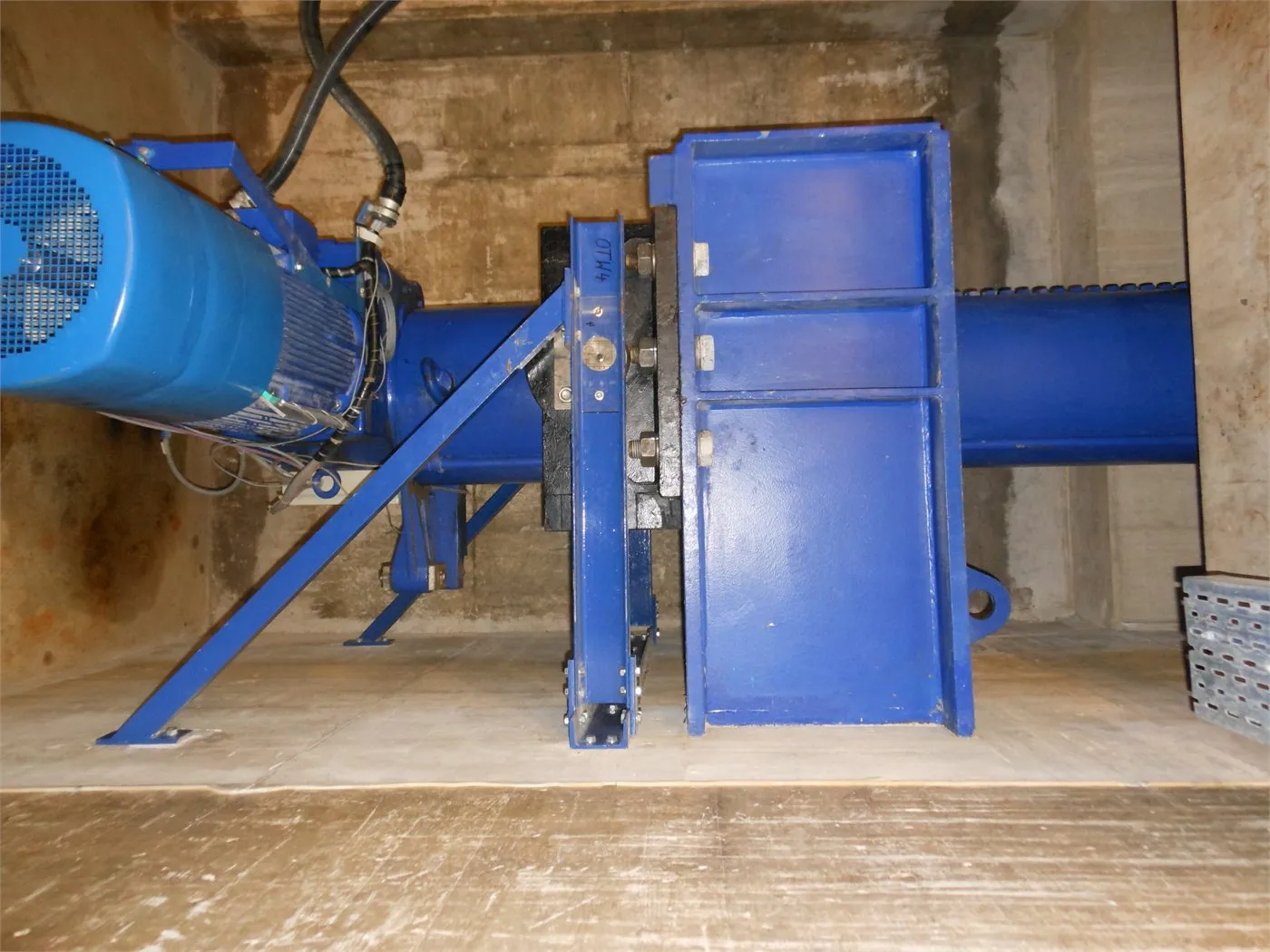
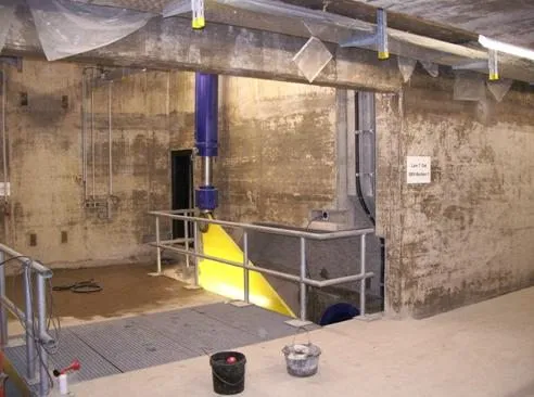
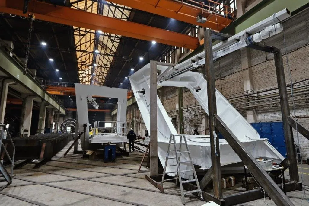
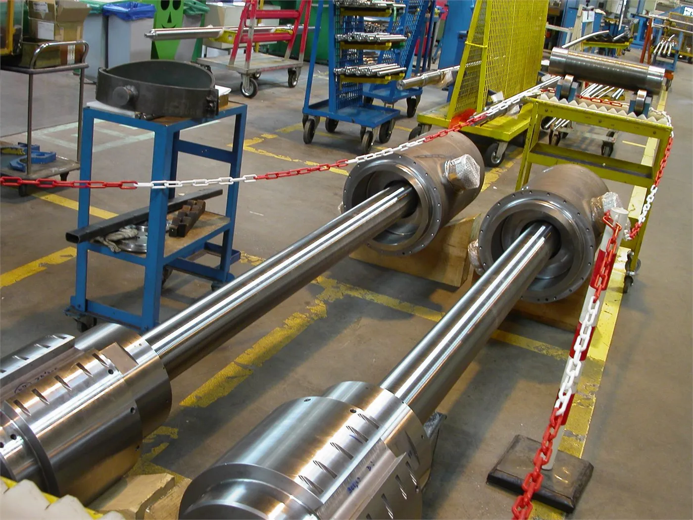
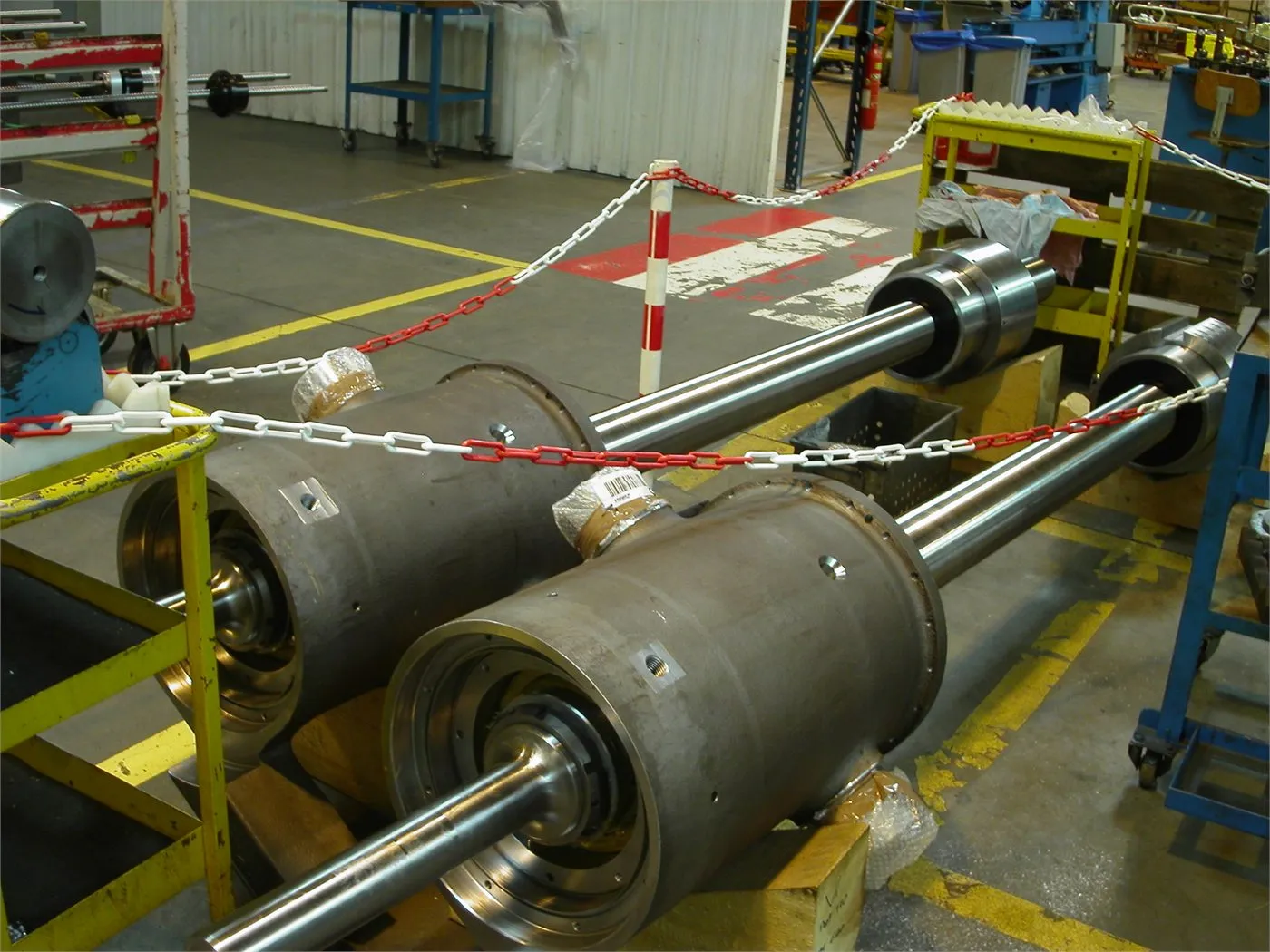
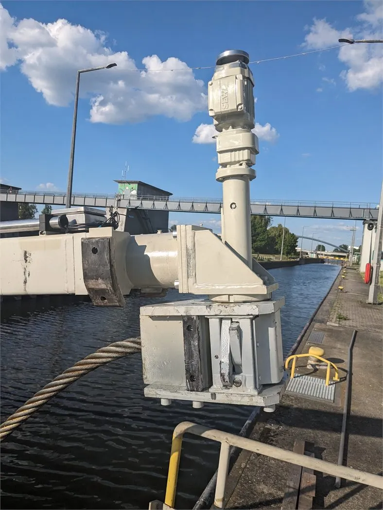
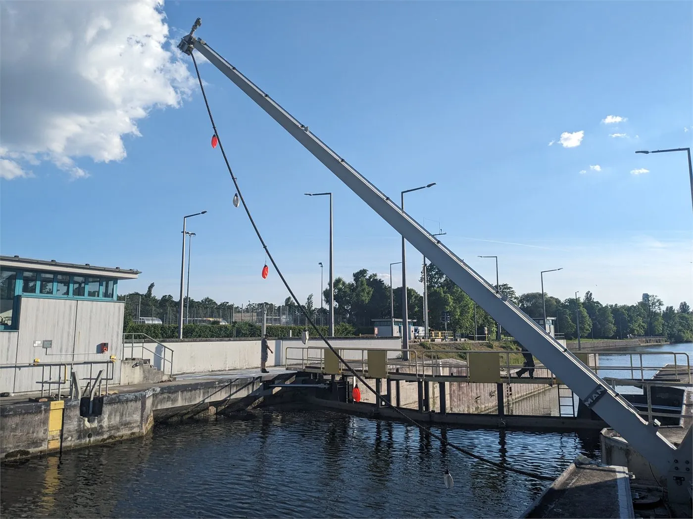
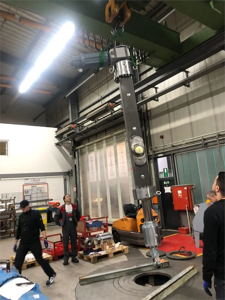
Application images
Views of assemblies, installation space and real operating environments.
The images show typical tasks in this industry: installation space, interfaces, drive position, mounting and environment become visible directly at the component.
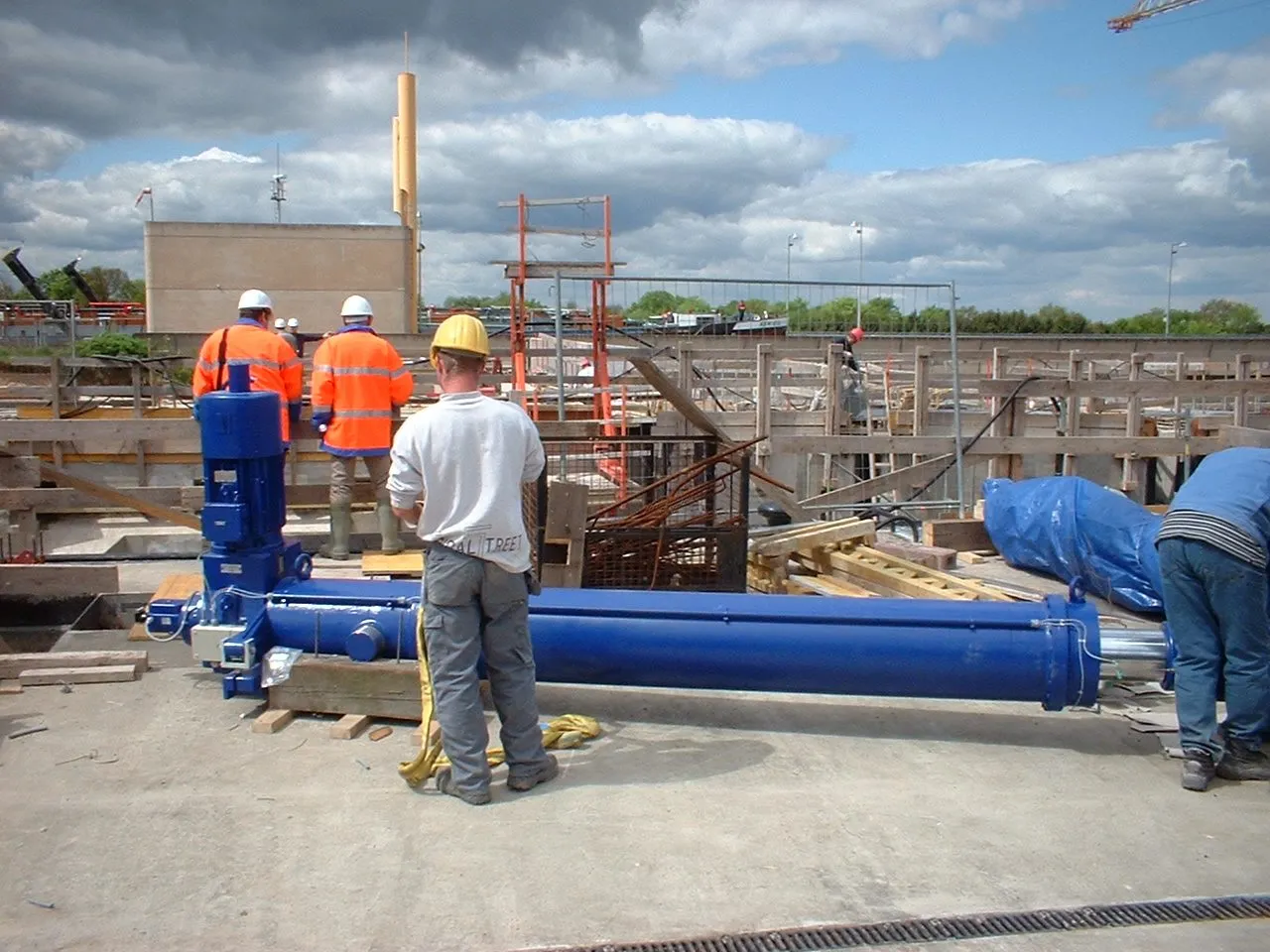
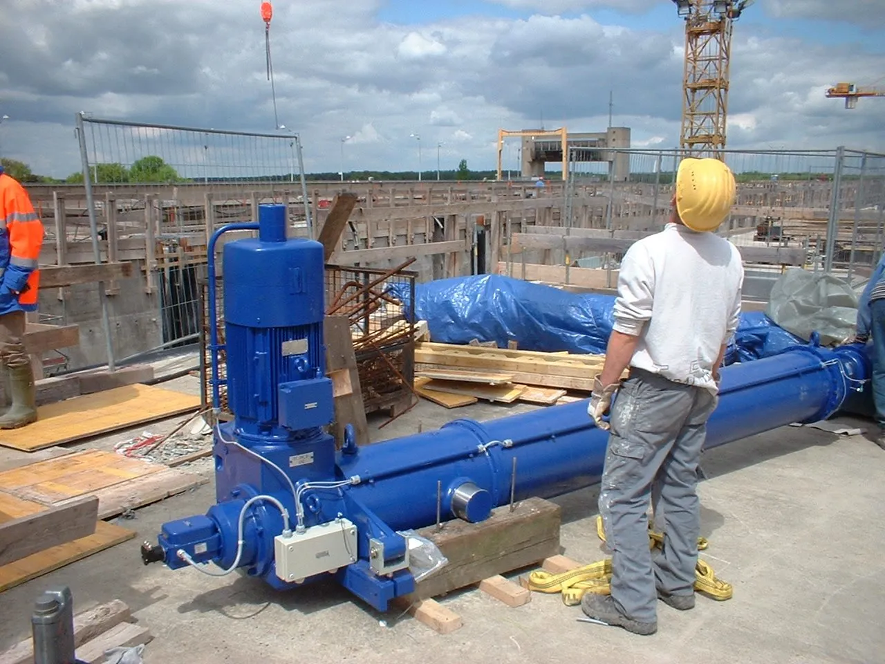
Real-world project examples
Similar tasks from real-world projects.
Real-world infrastructure project
Heavy-duty lock drive with 22 electric actuators
For a large lock system, S+R supplied 22 heavy electric actuators that move loads in the range of around 1,000 kN together.
Read project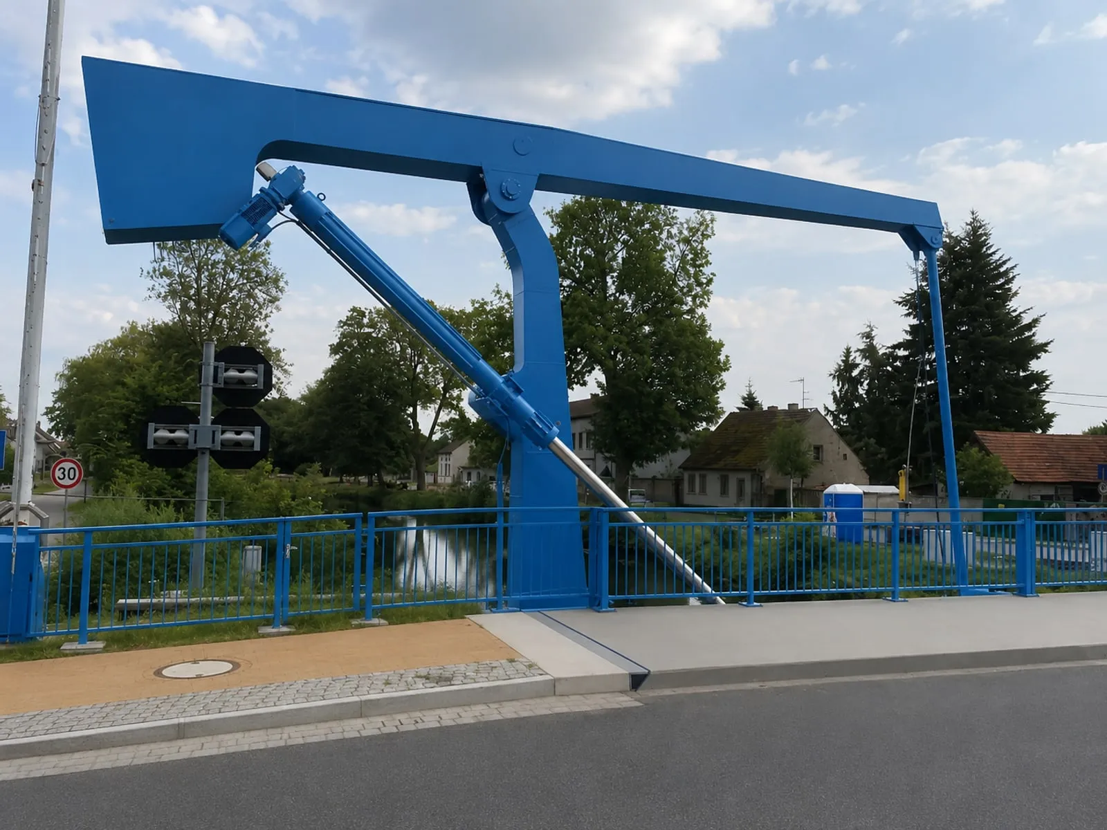
Real-world infrastructure project
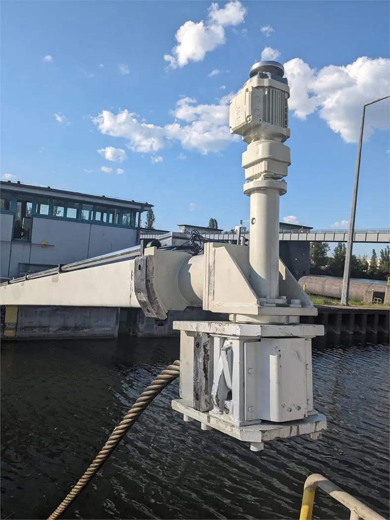
Bridge drive: four electric actuators of around 350 kN each for two movable bridges
Two movable bridges are opened and closed by four electric actuators of around 350 kN each - weatherproof, controlled and serviceable over the long term.
Read project Real-world infrastructure project
Heavy-duty actuator for a lock system after 20 years in service
A heavy electric actuator from a lock project returned to the S+R workshop after roughly 20 years in operation for service and service-life assessment.
Read project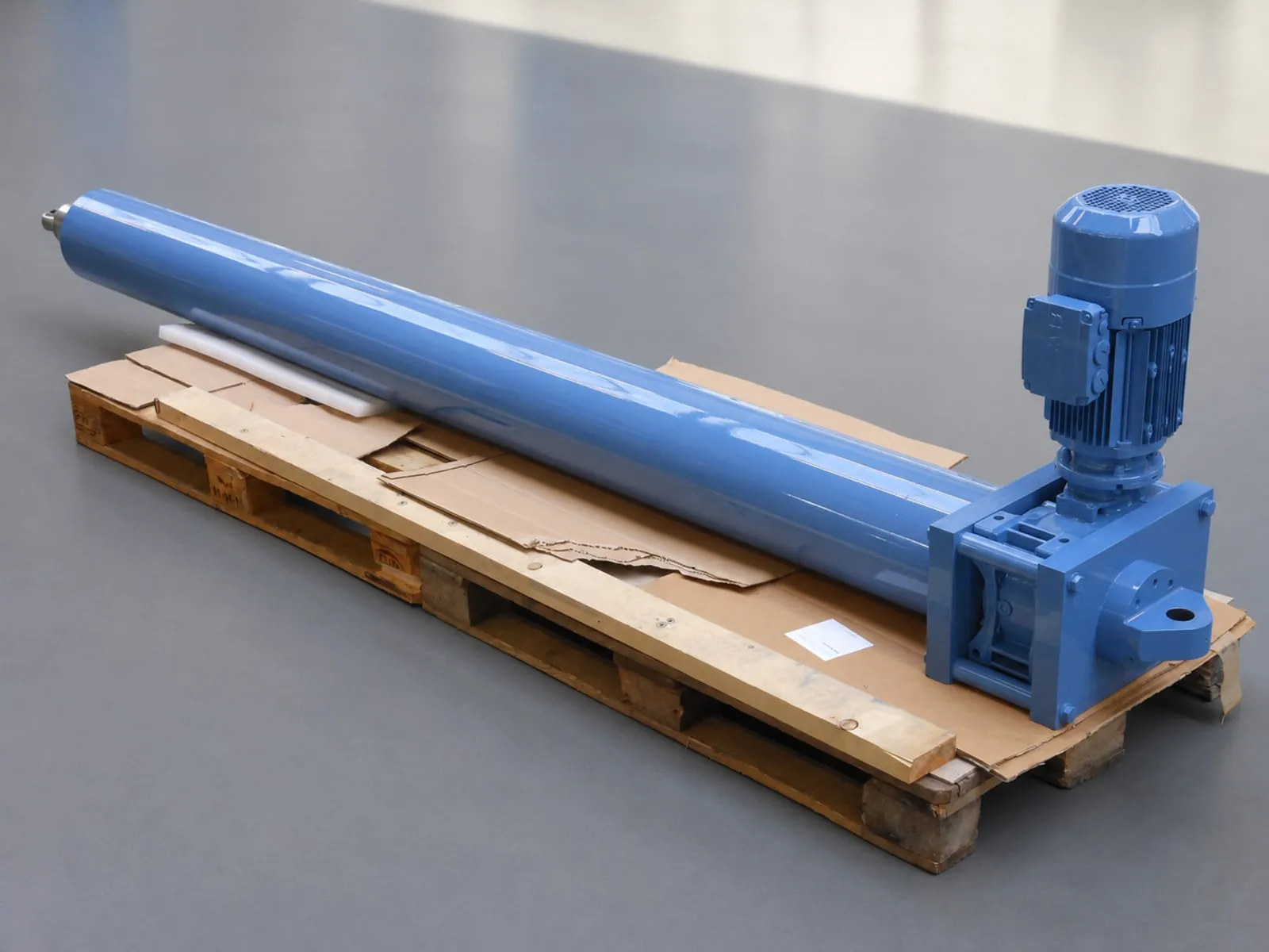
Real-world project example
Heavy-duty custom actuator for rough equipment
A robust electric actuator replaced a maintenance-heavy adjustment in a rough steelworks environment.
Read project