Axial motor mounting for direct force
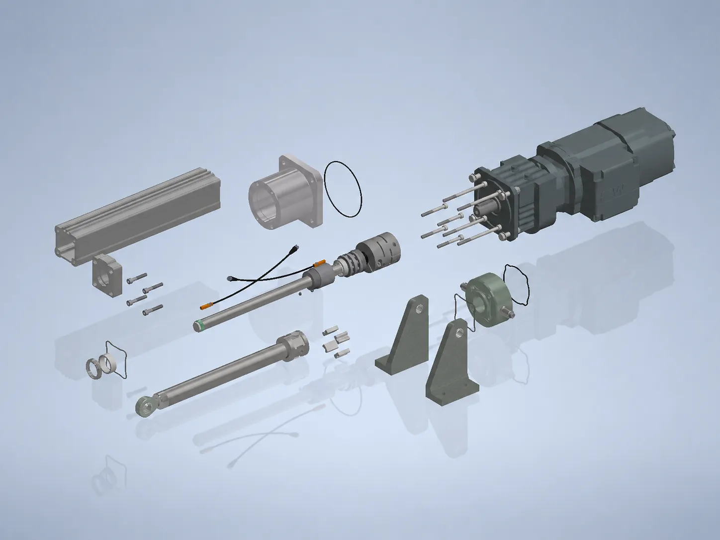
Motor and screw share one axis – the force line stays direct and easy to access.
- Axial motor mounting
- Direct force line without redirection
- High force density
- Good access for maintenance
 Linear Technology
 Knowledge · Decision aid
A, S and X are three proven design principles for electric linear actuators – not a rigid sales programme. This page helps engineers narrow down the right design principle as a starting point: by installation space, force line, maintenance access, environment, dynamics and protection need. S+R works out the final solution from the application.
A, S and X differ above all in how the motor is mounted and how protected the design is. A stands for the direct, axial force line, S for short installed lengths, X for the enclosed design in rough environments. What tips the balance is installation space, force line, environment, dynamics and service access. You do not have to fix the design yourself: from a rough description of the application, S+R derives the right design principle and develops an individual solution from it.
Starting point
Each principle is a proven starting point for an individual design – not the finished product. Every design covers the headline figures (up to 500 kN, 3,000 mm stroke, 1,000 mm/s, 100 % ED, IP65+); they differ in mounting, installation space and protection.
Motor and screw share one axis – the force line stays direct and easy to access.
The drive sits parallel or at an angle to the axis – the assembly stays short.
The drive technology is more fully enclosed – made for dirt, outdoor use and dynamics.
Comparison
The table compares the three design principles objectively. There is rarely a blanket “better” – what matters is which criterion tips the balance in your application.
| Criterion | A | S | X |
|---|---|---|---|
| Installation space | Needs axial space in line with the axis. | Short installed length thanks to parallel/angular mounting. | Compact, enclosed assembly. |
| Force line | Direct, axial force line without redirection. | Force via gearbox and key, drive offset. | Force via timing belt or chain to the screw. |
| Maintenance access | Motor and add-ons easy to access. | Check access early depending on motor position. | Enclosed – plan maintenance access deliberately. |
| Environment | Can be designed for rough industry and outdoor use (IP65+). | Protected motor compartment in tight modules. | More fully enclosed for dirt and outdoor use, EX possible. |
| Dynamics | Solid for positioning and synchronous tasks. | Designed for compact, integrated motion. | Suited to dynamic, frequent motion. |
| Protection need | Protection via component choice and bellows. | Motor compartment protected, assembly compact. | Highest protection of the drive technology (enclosed, overload protection). |
Practice
Which design principle suits best follows from the installation situation – not from a catalogue. Four typical starting situations.
High forces in a clear installation situation – the force line should stay direct and easy to access. Starting point: A.
View A series →Limited machine space or fixed existing installation space the assembly has to fit into. Starting point: S.
View S series →Dust, moisture, outdoor use or a poorly accessible installation position with dynamic motion. Starting point: X.
View X series →Fast, frequent strokes with defined position and data connection – A or, if more protection is needed, X, depending on installation space.
View A series →Decision
These questions pre-sort the design. You do not have to answer them conclusively – a rough estimate per point is enough, S+R clarifies the rest.
Enough room in line with the axis favours A with its direct force line. If space is tight, S moves to the front.
Dirt, moisture, outdoor use or EX requirements favour the enclosed X design – though A can also be specified for rugged use.
Little axial space or a fixed existing installation space favour the parallel or angular mounting of S.
If the drive should stay easy to reach, A has the edge. With enclosed designs such as X, maintenance access is planned deliberately.
Mounting, existing connection points and the control system all influence the design. A drawing or rough installation situation helps narrow down the starting point.
FAQ
No. The design is a starting point, not a commitment to order. Describe installation space, force, environment and service access – S+R proposes the right design principle and adapts it to your application.
A has the axial motor mounting with a direct force line, S the parallel or angular mounting for short installed lengths, and X the enclosed design with belt or chain drive for rough, hard-to-access systems.
They are proven design principles, not a rigid product logic. Motor, screw, mounting, sensors and protection class are specified per application; the result is a custom electric linear actuator.
In principle yes: up to about 500 kN, 3,000 mm stroke, 1,000 mm/s and 100 % ED, IP65+. What tips the balance is installation space, force line, environment, dynamics and service access – not the headline figures alone.
The sizing follows: which data on force, stroke, speed, duty cycle and environment S+R needs for an initial assessment is set out in the knowledge overview on sizing.
Installation space, force, environment and service access in keywords are enough. S+R proposes the right design principle – A, S or X – and develops a custom electric linear actuator from it.