Sizing
Sizing electric actuators
Determine force, stroke, speed, duty cycle and environment cleanly – for engineering and purchasing preparing a solid inquiry.
Learn more → Linear Technology
 Knowledge
The most important basics for engineering, purchasing and maintenance: structure, spindle choice, protection class, control, inquiry data and typical service questions.
In-depth topics
This overview explains the basics. For sizing, comparison, design, control, heavy-duty and retrofit, dedicated guides go deeper – each with the data we need for your inquiry.
Determine force, stroke, speed, duty cycle and environment cleanly – for engineering and purchasing preparing a solid inquiry.
Learn more →When an electric drive pays off over compressed air or oil – positioning, diagnostics, maintenance and infrastructure in direct comparison.
Learn more →Which design principle fits installation space, force line and environment – axial, parallel or protected mounting.
Learn more →Limit switches, encoders, positioning and synchronous control up to the handover at the motor terminal box – for control engineering and commissioning.
Learn more →Design for high continuous forces, long travel and harsh locations – hydraulic steel structures, foundries, test benches, special machinery.
Learn more →Replace, repair or re-engineer existing cylinders with an electric solution – including interfaces and service path.
Learn more →Function
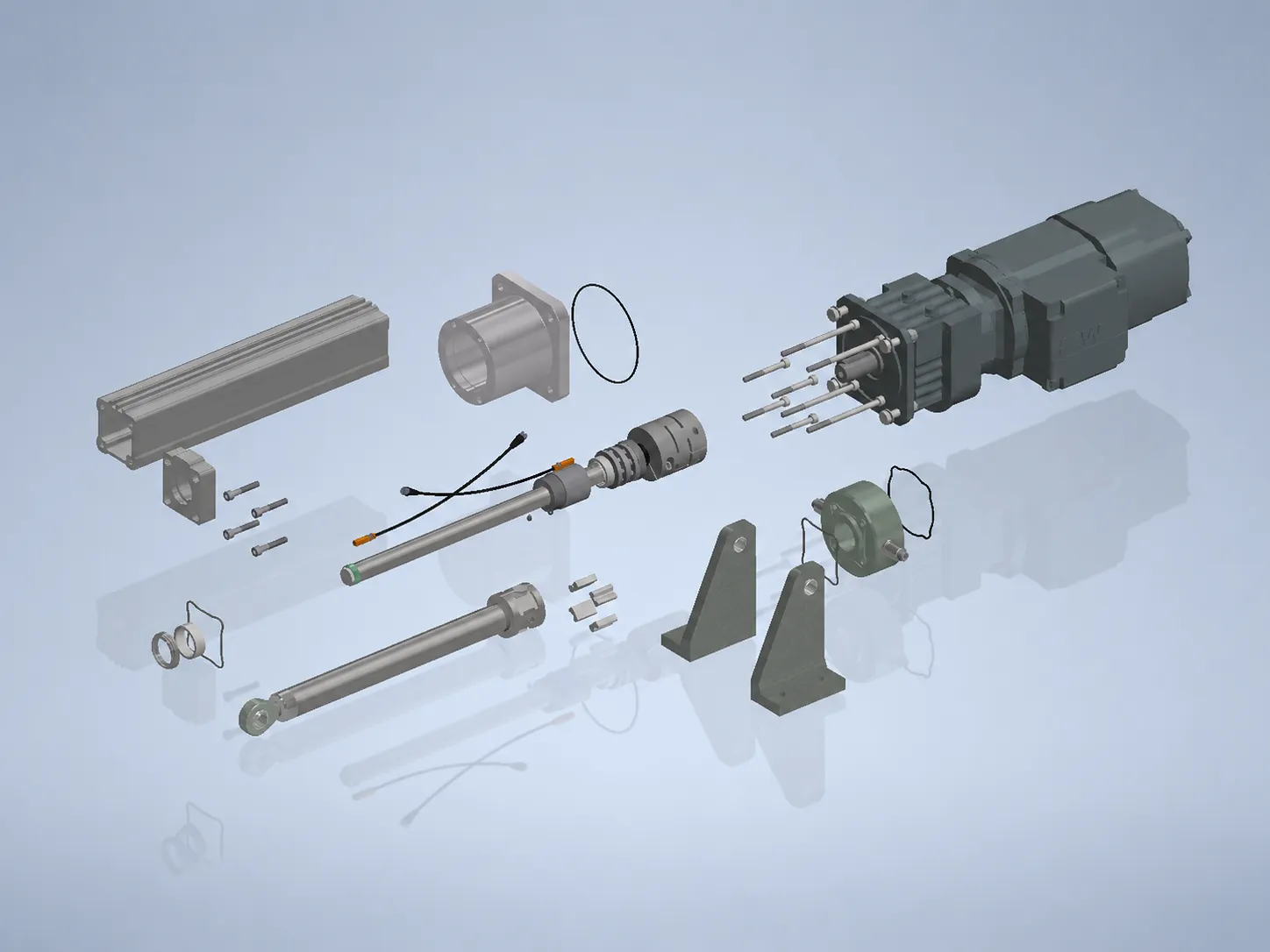
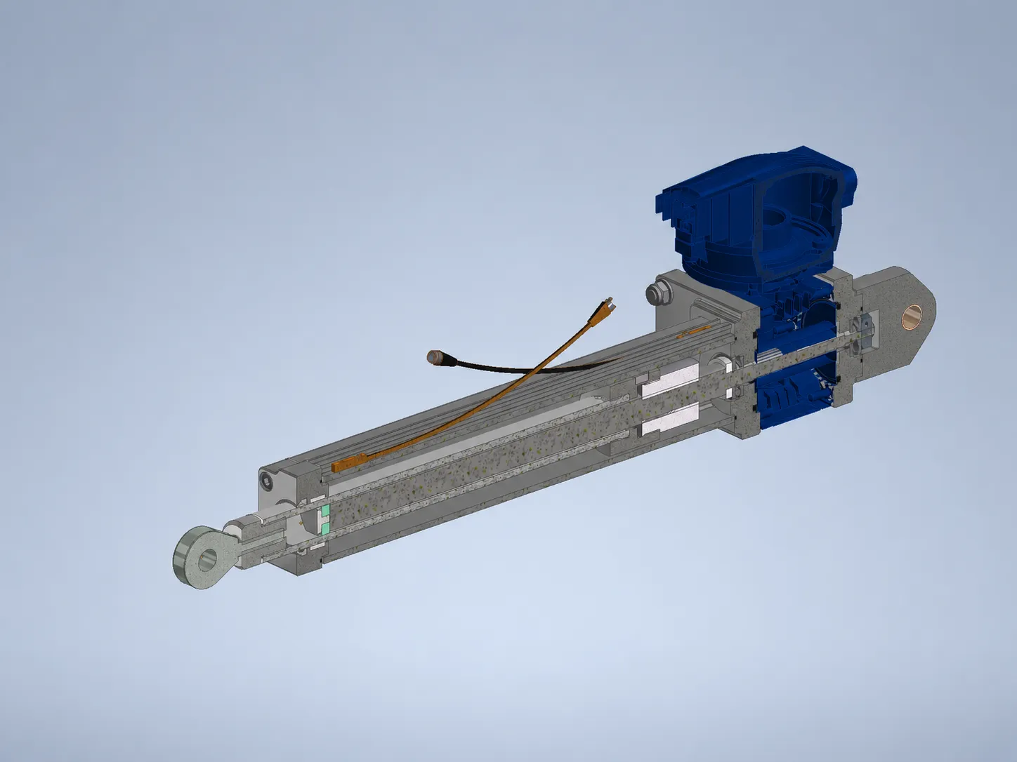
An electric motor drives a ball or trapezoidal screw via coupling, gearbox, timing belt or chain. The nut converts rotation into stroke motion; piston tube, guides, bearings, seals and mounting interfaces transfer force and motion into the machine – built axially, parallel or protected depending on the series.
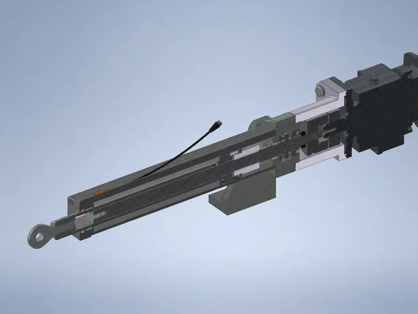
Direct force line, good access and high force density when axial installation space is available.
Short installed length and flexible motor position when the machine geometry leaves little axial space.
For rougher environments, hard-to-access systems or dynamic tasks with belt or chain principle.
For high speed, high duty cycle, repeatability, dynamic applications and high efficiency.
For lower speed, lower duty cycle, robust cost structure and applications where self-locking is desired.
Limit switches, potentiometers, encoders, positioning control or synchronous control are derived from the machine function.
Sensors & control
Limit switches, potentiometers, encoders, positioning control or synchronous control are not an add-on list; they are part of the function. Position is handed over to your control system as 0–10 V or 4–20 mA; the electrical interface is the motor terminal box, so cabinet and commissioning stay control-open on your side.
Learn more: control & feedback – end positions, position, interface →
Protection & environment
Dust, moisture, outdoor use and cleaning environments determine sealing and design.
Overload clutch, end positions, self-locking and holding function are evaluated technically – especially carefully at high continuous forces.
Mounting, installation space and existing drawing determine standard or custom solution.
FAQ
An electric linear actuator converts the rotation of an electric motor into controlled linear stroke motion via a ball or trapezoidal screw. In many applications it replaces pneumatic or hydraulic cylinders with electrically controlled, media-free motion.
Yes. The design range extends from modified standard products to complete custom engineering.
Force, stroke, speed, voltage, duty cycle, installation space, environment, protection class, control, quantity and drawing.
The standard programme reaches up to about 80 kN, project-specific heavy-duty solutions up to about 500 kN. Stroke up to about 3,000 mm is possible depending on the design.
Up to about 1,000 mm/s depending on screw, load and size. Ball screws suit high speed and duty cycle, trapezoidal screws suit slower, self-locking motion.
Limit switches, potentiometer, encoder, positioning control or synchronous control. Position can be provided as an analog signal (0–10 V or 4–20 mA) to your control system; the electrical interface is the motor terminal box.
A stands for a direct axial force line, S for parallel or angular mounting in tight installation spaces, X for a protected design in rough environments or dynamic tasks. The right series follows from installation space, force line, environment and dynamics.
Above all when defined intermediate positions, feedback, diagnostics, media-free operation, maintainability and a well documented interface matter.
Yes. Repair, spare parts and retrofit are a dedicated inquiry path.
Inquiry
Send us your key data – force, stroke, speed, environment and interface. From that we derive series, screw and protection class.