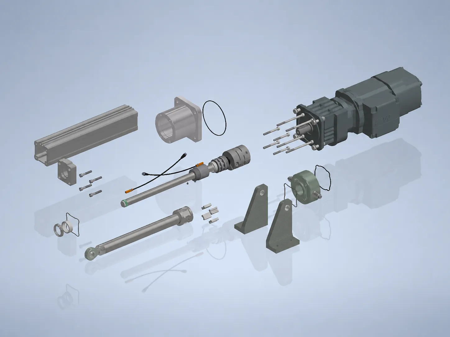
Axial motor mounting for direct force
Motor and screw share one axis – the force line stays direct and easy to access.
- Axial motor mounting
- Direct force line without redirection
- High force density
- Good access for maintenance
Knowledge · Decision aid
AP, SP and XP are three proven design principles for electric linear actuators – not a rigid sales programme. This page helps engineers narrow down the right design principle as a starting point: by installation space, force line, maintenance access, environment, dynamics and protection need. S+R works out the final solution from the application.
AP, SP and XP differ above all in how the motor is mounted and how protected the design is. AP stands for the direct, axial force line, SP for short installed lengths, XP for the enclosed design in rough environments. What tips the balance is installation space, force line, environment, dynamics and service access. You do not have to fix the design yourself: from a rough description of the application, S+R derives the right design principle and develops an individual solution from it.
Starting point
Each principle is a proven starting point for an individual design – not the finished product. Every design covers the headline figures (up to 500 kN, 3,000 mm stroke, 1,000 mm/s, 100 % ED, IP65+); they differ in mounting, installation space and protection.
Motor and screw share one axis – the force line stays direct and easy to access.
The drive sits parallel or at an angle to the axis – the assembly stays short.
The drive technology is more fully enclosed – made for dirt, outdoor use and dynamics.
Comparison
The table compares the three design principles objectively. There is rarely a blanket “better” – what matters is which criterion tips the balance in your application.
| Criterion | AP | SP | XP |
|---|---|---|---|
| Installation space | Needs axial space in line with the axis. | Short installed length thanks to parallel/angular mounting. | Compact, enclosed assembly. |
| Force line | Direct, axial force line without redirection. | Force via gearbox and key, drive offset. | Force via timing belt or chain to the screw. |
| Maintenance access | Motor and add-ons easy to access. | Check access early depending on motor position. | Enclosed – plan maintenance access deliberately. |
| Environment | Can be designed for rough industry and outdoor use (IP65+). | Protected motor compartment in tight modules. | More fully enclosed for dirt and outdoor use, EX possible. |
| Dynamics | Solid for positioning and synchronous tasks. | Designed for compact, integrated motion. | Suited to dynamic, frequent motion. |
| Protection need | Protection via component choice and bellows. | Motor compartment protected, assembly compact. | Highest protection of the drive technology (enclosed, overload protection). |
Practice
Which design principle suits best follows from the installation situation – not from a catalogue. Four typical starting situations.
High forces in a clear installation situation – the force line should stay direct and easy to access. Starting point: AP.
View AP series →Limited machine space or fixed existing installation space the assembly has to fit into. Starting point: SP.
View SP series →Dust, moisture, outdoor use or a poorly accessible installation position with dynamic motion. Starting point: XP.
View XP series →Fast, frequent strokes with defined position and data connection – AP or, if more protection is needed, XP, depending on installation space.
View AP series →Decision
These questions pre-sort the design. You do not have to answer them conclusively – a rough estimate per point is enough, S+R clarifies the rest.
Enough room in line with the axis favours AP with its direct force line. If space is tight, SP moves to the front.
Dirt, moisture, outdoor use or EX requirements favour the enclosed XP design – though AP can also be specified for rugged use.
Little axial space or a fixed existing installation space favour the parallel or angular mounting of SP.
If the drive should stay easy to reach, AP has the edge. With enclosed designs such as XP, maintenance access is planned deliberately.
Mounting, existing connection points and the control system all influence the design. A drawing or rough installation situation helps narrow down the starting point.
FAQ
No. The design is a starting point, not a commitment to order. Describe installation space, force, environment and service access – S+R proposes the right design principle and adapts it to your application.
AP has the axial motor mounting with a direct force line, SP the parallel or angular mounting for short installed lengths, and XP the enclosed design with belt or chain drive for rough, hard-to-access systems.
They are proven design principles, not a rigid product logic. Motor, screw, mounting, sensors and protection class are specified per application; the result is a custom electric linear actuator.
In principle yes: up to about 500 kN, 3,000 mm stroke, 1,000 mm/s and 100 % ED, IP65+. What tips the balance is installation space, force line, environment, dynamics and service access – not the headline figures alone.
The sizing follows: which data on force, stroke, speed, duty cycle and environment S+R needs for an initial assessment is set out in the knowledge overview on sizing.
Installation space, force, environment and service access in keywords are enough. S+R proposes the right design principle – AP, SP or XP – and develops a custom electric linear actuator from it.